Overview:
This project leverages the powerful ESP32 platform to create a versatile IoT control system. Its modular architecture supports a wide range of features such as real-time control, sensor integration, UI display, and network communication. Understand the basics of how IoT devices work, how they connect to and communicate with other devices in their network, and how they can be programmed to perform tasks.
Hands-on experience & Practical Knowledge
- Individuals who are simply curious about how robots work,
- Students taking their first steps into electronics,
- Educators, as modular prototyping device for concept demos,
- Hobbyists looking to explore robotics.
Espresso [Otomato]

Features & Capabilities
- Versatile IoT Controller Devicewith Bluetooth and Wi-Fi functionalities
- Smart Displays , LEDs for colorful patterns and a buzzer for sounds
- Applications include smart clock, IoT Controller, Pomodoro
Learn:
- Fundamental concepts of IoT
- Input Sensors signal reading for Device Control
- Network Communication WiFi Protocol
- IoT programming concepts [hardware with code]
- Networking & IoT Control
An Open-Source DIY IoT Robot.
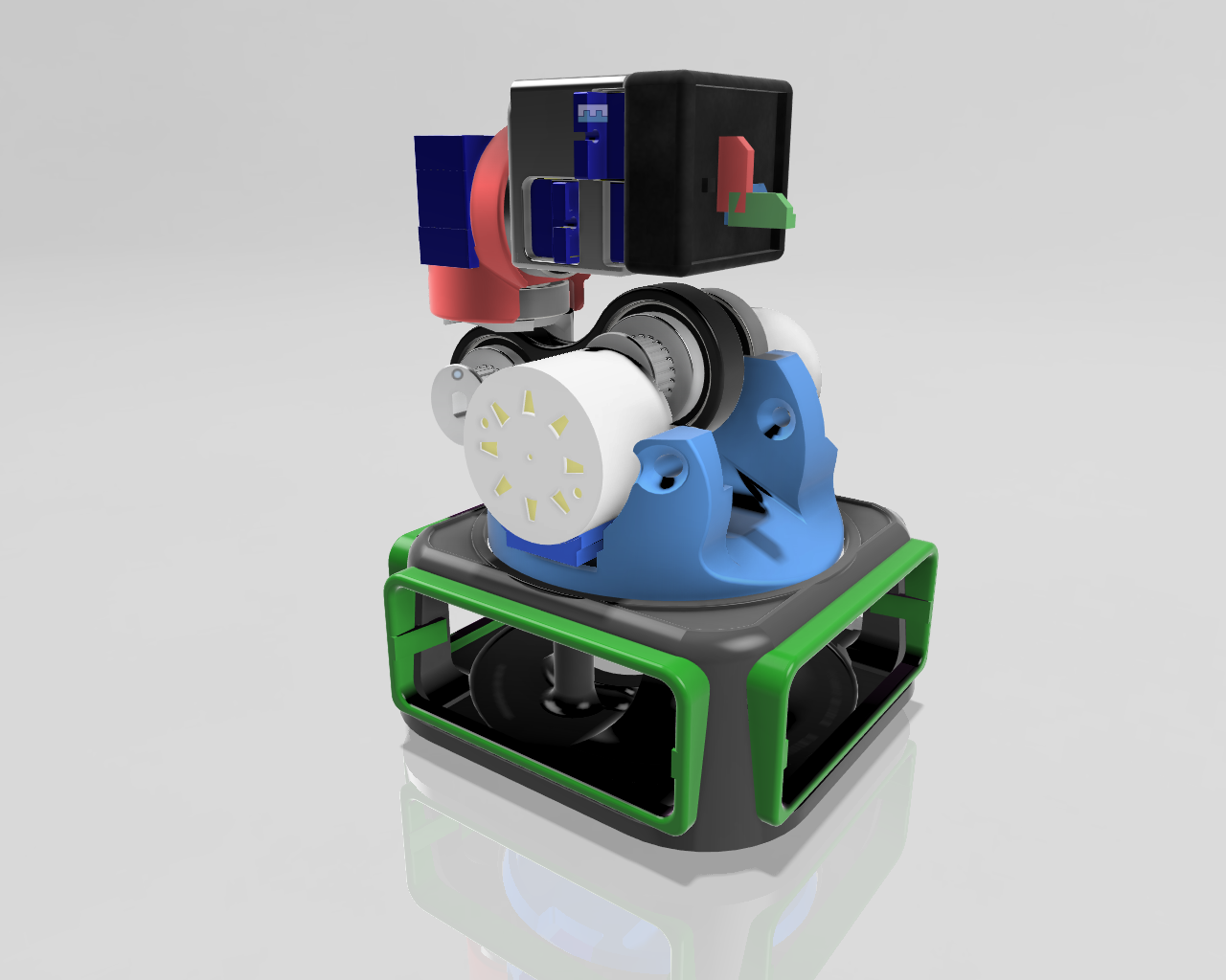
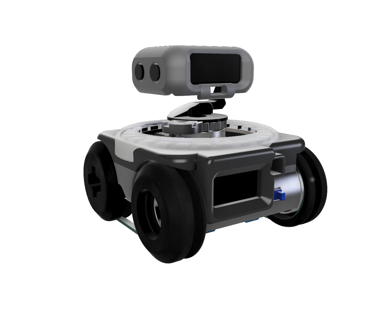
This guide will walk you through the electronic components of the ESPRESSO robot.
We’ll be connecting servos, an RGB LED ring, OLED displays, a buzzer and a Time-of-Flight sensor, all powered by a LiPo battery with a battery management system.
Components
- ESP32 C3 Supermini Microcontroller
- 1 x Servos
- 2 x Servos (Continuos Rotation)
- WS2812 Neopixel Ring
- SSD1306 OLED Display 128×64
- SSD1306 OLED Display 128×32
- Buzzer
- VL53L0X1 Time-of-Flight Sensor
- LiPo Battery (3.7V)
- BMS MH-CD42 Battery Management System
- 3.3V Regulator
- ON/OFF Switch
- Jumper Wires
Wiring Diagram

Connecting the Components
(Step 1: Power Supply and ON/OFF Switch)
Connect the LiPo battery to the BMS MH-CD42 module.
- Connect the positive (+) terminal of the LiPo battery to the “+” input on the BMS.
- Connect the negative (-) terminal of the LiPo battery to the “-” input on the BMS.
Connect the ON/OFF Switch to the BMS MH-CD42 module. - Cut the positive wire connected to the “+” on the BMS and Connect it to one end of the ON/OFF Switch.
- Connect the other end of the ON/OFF Switch to the “+” output on the BMS.
Diagram Description: The diagram should show the LiPo battery connected to the BMS, and the switch connected on the positive wire after the BMS. Highlight the battery, BMS and the switch in the diagram with the newly added wires.
(Step 2: 5V Power Distribution)
Connect the BMS output to the Servos.
- Connect the “+” on the Servos to the “+” output on the BMS.
- Connect the “-” on the Servos to the “-” output on the BMS.
Connect the BMS output to the WS2812 Neopixel Ring. - Connect the “+” on the RGB Ring to the “+” output on the BMS.
- Connect the “-” on the RGB Ring to the “-” output on the BMS.
Diagram Description: The diagram should show the same setup in step 1 but with the “+” and “-” wires extended to power the 3 Servos and the RGB ring. Highlight the Servos and RGB ring with the wires added to them.
(Step 3: 3.3V Regulator Connection)
Connect the output of the BMS to the 3.3V Regulator.
- Connect the “+” output of the BMS to the input of the 3.3V regulator.
- Connect the “-” output of the BMS to the ground pin of the 3.3V regulator.
Diagram Description: The diagram should now show the wires extending from the output of the BMS to the input of the 3.3V regulator. Highlight the regulator and the wires added.

(Step 4: Powering the ESP32)
Connect the 3.3V regulator output to the ESP32.
- Connect the 3.3V output from the regulator to the VCC (or 3.3V) pin on the ESP32.
- Connect the GND from the regulator to the GND pin on the ESP32.
Diagram Description: Show the 3.3V regulator now connected to the ESP32. Highlight the ESP32 and the connected wires.
(Step 5: Powering the OLEDs and ToF Sensor)
Connect the 3.3V regulator output to the OLEDs and ToF Sensor.
- Connect the 3.3V output from the regulator to the VCC pin on both OLED displays and the VL53L0X1 sensor.
- Connect the GND from the regulator to the GND pin on both OLED displays and the VL53L0X1 sensor.
Diagram Description: Show the 3.3V regulator connected to the two OLED displays and the ToF sensor. Highlight the connected components.
(Step 6: I2C Connections)
Connect the I2C communication lines.
- Connect the SDA pin of the ESP32 to the SDA pin of both OLED displays and the VL53L0X1 sensor.
- Connect the SCL pin of the ESP32 to the SCL pin of both OLED displays and the VL53L0X1 sensor.
Diagram Description: Show the SDA (Blue) and SCL (Yellow) wires connecting the ESP32 to both OLEDs and the ToF sensor. Highlight the I2C connections.

(Step 7: Servo Signal Connections)
Connect the signal pins of the servos to the ESP32.
- Connect the signal wire of SERVO_R to digital pin 6 on the ESP32.
- Connect the signal wire of SERVO_L to digital pin 5 on the ESP32.
- Connect the signal wire of SERVO_H to digital pin 7 on the ESP32.
Diagram Description: Shows the signal wires (green) from each servo connecting to the specified digital pins on the ESP32.
(Step 8: WS2812 Signal Connections)
Connect the WS2812 Signal pin to the ESP32.
- Connect the signal wire of the RGB ring to digital pin 10 on the ESP32.
Diagram Description: Shows the signal wire (Orange) from the RGB ring connecting to digital pin 10.
Important Considerations:
Power Supply and Voltage Regulation:
Decoupling Capacitors:
Add decoupling capacitors close to the power pins of every active component (ESP32, OLED displays, VL53L0X1, Servos, and RGB Ring). These capacitors smooth out voltage fluctuations and provide local energy storage, which is crucial for reliable operation.
– ESP32: Place a 0.1µF (100nF) ceramic capacitor as close as possible to the 3.3V and GND pins. A larger electrolytic capacitor (e.g., 10µF) in parallel can also help with larger voltage dips.
– OLED Displays: 0.1µF ceramic capacitor close to VCC and GND.
– VL53L0X1: 0.1µF ceramic capacitor close to VCC and GND.
– Servos: Place a larger electrolytic capacitor (e.g., 470µF or 1000µF) across the 5V power rail near the servo power connections. Servos can draw significant current spikes when they move, which can cause voltage drops if the power supply isn’t adequately filtered.
– RGB Ring: 0.1µF ceramic capacitor close to VCC and GND.
Voltage Regulator Stability:
Add capacitors to the input and output of the 3.3V regulator. Consult the regulator’s datasheet for the recommended capacitor values (typically a 1µF ceramic capacitor on the input and a 10µF electrolytic capacitor on the output). This helps stabilize the regulator and prevent oscillations.
- BMS MH-CD42: Verify the output voltage and current capabilities of the BMS module under load. Make sure it can supply enough current for all the components, especially the servos and RGB ring when they are operating simultaneously. If the BMS has an enable pin, consider using it to shut down the robot completely when not in use.
Signal Integrity and Noise Reduction:
- I2C Pull-up Resistors: The I2C bus requires pull-up resistors on the SDA and SCL lines. The diagram doesn’t explicitly show these. Typical values are 4.7kΩ, but you might need to experiment to find the optimal values for your setup. Connect one resistor from SDA to 3.3V and another from SCL to 3.3V.
- Servo Signal Filtering: If you experience jitter or erratic behavior from the servos, consider adding a small capacitor (e.g., 100pF) between the servo signal pin and GND. This can help filter out noise on the signal line.
- Keep wires short: Use shorter wires to connect components. Longer wires act like antennas and pick up more noise.
Other Considerations:
- Buzzer Protection: Add a current-limiting resistor in series with the buzzer to prevent it from drawing too much current from the ESP32 pin. A value between 100Ω and 470Ω should be sufficient.
- Fuse Protection: Add a fuse between the LiPo battery and the BMS module. This will protect the battery and the rest of the circuit from overcurrent conditions.
- Test Points: Include test points on key voltage and signal lines. This makes it easier to debug the circuit during development.
Reasoning:
- Capacitors: Capacitors store electrical energy and can quickly provide current when needed. Decoupling capacitors help to stabilize the power supply by filtering out noise and voltage spikes. This is especially important for digital circuits that switch rapidly.
- Pull-up Resistors: The I2C protocol uses open-drain outputs, which means that devices can only pull the SDA and SCL lines low. Pull-up resistors are needed to pull the lines high when no device is actively pulling them low.
- Noise Reduction: Noise can cause erratic behavior in electronic circuits. Filtering techniques help to reduce noise and improve the reliability of the circuit.
By implementing these suggestions, you can improve the robustness, reliability, and performance of the robot’s circuit design.
- Double-check all connections before powering on.
- Ensure the polarity of the battery and connections is correct.
- When uploading code to the ESP32, make sure you have selected the correct board and COM port in your Arduino IDE or other development environment.
Disclaimer:
This guide is for informational purposes only. Be careful when working with electronics and always take appropriate safety precautions. I am not responsible for any damage or injury resulting from following this guide.
Hardware Overview
Core Components:Z
- ESP32 LIVE MINI KIT: The heart of the system, with dual-core processing at 240MHz, capable of handling complex tasks.
- Displays:
- 32×128 OLED (I2C, address 0x3C): Used for static and dynamic information display.
- 128×64 OLED (I2C, address 0x3D): Additional display for detailed data.
- TFT Round Display ( SCLK[18] MOSI[23] MISO[19] CS[5] BL[36] RS[26] )
- Inputs:
- Rotary Potentiometer: Analog input for variable control (e.g., volume, speed).
- Push Buttons: Simple digital inputs for commands.
- 5 way navigation keypad
- Joystick: 2-axis analog controls.
- Rotary Encoder: For fine control and menu navigation.
- Sensors:
- MPU6050: Accelerometer and gyroscope for orientation and motion sensing.
- Outputs:
- Buzzer: Audio feedback.
- WS2812 RGB LEDs: Visual indicators with color control.
Communication
For sensor and peripheral communication
- I2C
- SPI
- UART
Connectivity:
- WiFi: For network communication, remote control, and OTA updates.
3. Setting Up Your Environment
Tools Needed:
- Hardware:
- ESP32 LIVE MINI KIT
- Connecting wires, breadboards, prototyping supplies
- Software:
- PlatformIO (recommended) or Arduino IDE
- USB cable for programming
- Testing equipment (multimeter, logic analyzer optional)
Installing Development Tools:
- Download and install PlatformIO IDE (recommended) or Arduino IDE.
- Clone or download the project repository from GitHub (if available).
- Install necessary libraries (see the project documentation).
4. Building the Hardware
Wiring Overview:
- Connect displays, sensors, buttons, joystick, encoder, and LEDs according to the pin mappings.
- Keep wiring neat to avoid short circuits.
- Use the pin overview diagram included in the documentation for reference.
Tips:
- Double-check connections before powering the system.
- Use appropriate resistors and level shifters if needed.
5. Programming Your Device
Compiling and Uploading:
- Open the project in your IDE.
- Configure hardware pin assignments if customizing.
- Build the firmware.
- Flash the firmware onto the ESP32.
- Observe the startup logs via serial monitor.
Key Code Structure:
- Hardware Abstraction Layer (HAL): Interfaces for all hardware components.
- Service Layer: Handles data storage, network, and background tasks.
- Application Layer: Manages user interfaces and core functionalities.
- UI Framework: Renders information on OLEDs, manages user interactions.
6. Exploring Key Features
UI System:
- Static screens with animations.
- Dynamic widgets like buttons, sliders, and menus.
- Screen transitions and state persistence.
Sensor Data:
- Reading accelerometer and gyroscope data in real-time.
- Displaying motion data on screens.
- Using sensor input for control or automation.
Network Communication:
- Connecting to WiFi networks.
- Sending and receiving data over MQTT or HTTP.
- Performing OTA updates for firmware upgrades.
Output Control:
- Using buttons and joystick for controlling outputs.
- Visual feedback via RGB LEDs and buzzer.
7. Developing Your Own Applications
Start with the provided application templates:
- Custom dashboards
- Data logger
- Remote control interfaces
Modify the UI and logic to suit your project:
- Add new input methods
- Integrate additional sensors
- Connect to cloud services
8. Extending the System
Plugins & Modular Design:
- Develop new modules for sensors
- ├── Apps (menu)
- ├── Clock (Application)
- ├── Timer (Stopwatch Application)
- └── Pomodoro Timer
- ├── SYS Info (System Monitoring Application)
- ├── IoT DEV (menu)
- ├── System (menu)
- ├── LED (RGB Led Control Application)
- ├── Network (menu)
- ├── System (menu)
- └── Network (menu)
- ├── Status (Network Monitoring Application)
- ├── Config (Network Configuration Application)
- └── WiFi (WiFi Configuration Application)
🎯 Workshop Flow
- Session 1: Introduction to ESP32 and components, wiring basics
- Session 2: Breadboard prototyping and sensor testing
- Session 3: Software setup, HAL and service layer development
- Session 4: UI and application logic, display integration
- Session 5: Final assembly, testing, and deployment
🟢 1. Introduction to ESP32 and Peripheral Modules
ESP32 LIVE MINI KIT Overview
- Dual-core 240MHz processor
- 520KB SRAM, 4MB Flash
- Integrated WiFi and Bluetooth
- Rich GPIO and peripheral support
Peripheral Modules
- Displays:
- TFT 1,9″ Display (SPI)
- 32×128 & 128×64 OLEDs (I2C)
- Inputs:
- Rotary Encoder & Potentiometer
- PSP Joystick
- 5-way Navigation Keypad
- Sensors:
- MPU6050 (Accelerometer + Gyroscope)
- Outputs:
- WS2812 RGB LED Strip
- Buzzer
🏗️ 2. Project Architecture, Design & Build
🔩 Hardware Design
Hardware Components Overview
- ESP32 LIVE MINI KIT
- TFT & OLED displays
- Joystick, keypad, rotary encoder/pot
- MPU6050 sensor
- RGB LED strip, buzzer
Pin Selection, Mapping & Wiring
| Component | Interface | Pins Used |
|---|---|---|
| TFT Round Display | SPI | SCLK[18], MOSI[23], MISO[19], CS[5], BL[36], RS[26] |
| OLED 32×128 / 128×64 | I2C | SDA[21], SCL[22], Addr: 0x3C / 0x3D |
| Rotary Encoder | Digital | A[10], B[23], SW[15] |
| Rotary Potentiometer | ADC | ADC2[36] |
| Navigation Keypad | Digital | UP[27], DW[25], L[32], R[12], C[33], SEL[14], CCL[19] |
| PSP Joystick | Analog | X[39], Y[35] |
| MPU6050 | I2C | SDA[21], SCL[22], Addr: 0x68 |
| WS2812 LED Strip | Digital | Pin[16] |
| Buzzer | PWM | Pin[17] |
Communication Protocols Implemented
- I2C: For sensors and OLEDs
- SPI: For TFT display
- UART: For external MCU communication
- PWM: For buzzer and LED brightness control
- ADC: For analog input from potentiometer and joystick
🧰 Tools, Parts & Materials Required
- ESP32 LIVE MINI KIT
- OLED & TFT displays
- Joystick, keypad, rotary encoder/pot
- MPU6050 sensor
- WS2812 LED strip, buzzer
- Breadboard, jumper wires, resistors
- Soldering iron, multimeter
- 3D printed enclosure parts (optional)
- PCB design software (e.g., KiCad, EasyEDA)
🔧 Hardware Assembly
- Wiring: Connect components per pin mapping table
- Soldering: Secure connections for reliability
- 3D Printed Parts: Mount displays, joystick, and keypad
- Circuit Board Design:
- Use KiCad/EasyEDA to design custom PCB
- Route traces for power, I2C, SPI, and GPIO
- Breadboard Prototyping:
- Validate each module individually
- Test communication protocols and input/output behavior
💻 Software Design
Code Architecture Overview
- Modular, layered architecture for scalability
- Separation of hardware logic, services, and UI
Hardware Abstraction Layer (HAL)
- Drivers for each peripheral (e.g., MPU6050, OLED, TFT)
- GPIO configuration and interrupt handling
- I2C/SPI/UART wrappers
Service Layer
- Sensor data acquisition
- Input event processing (e.g., joystick, keypad)
- Display rendering services
- LED and buzzer control logic
Application Layer
- Core logic for device behavior
- State management and task scheduling
- Communication with external devices via UART/WiFi
UI Framework
- Menu navigation using keypad and joystick
- Real-time sensor data visualization on OLED/TFT
- Status indicators via RGB LEDs
🛠️ 3. Project Build
💻 Software / Build Environment Setup
- IDE: VS Code with PlatformIO or Arduino IDE
- Libraries:
Adafruit_GFX,Adafruit_SSD1306for OLEDFastLEDfor WS2812Wire,SPI,Encoder,MPU6050libraries
- Toolchains:
- ESP-IDF or Arduino framework
- Version Control: Git for codebase management


