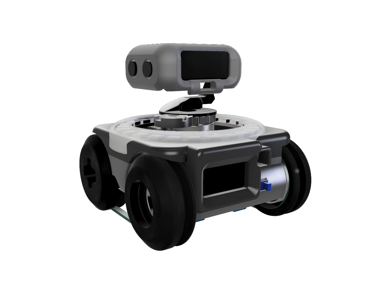
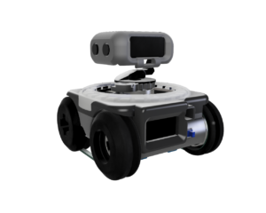
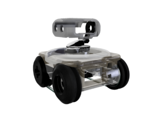
Overview:
A differential wheeled robot that combines various sensors, actuators, and a microcontroller.
As part of our eco-system learning platform, will help you understand fundamental concepts of how robot rovers work, how they sense their environment by mapping, and how they can be programmed for navigation.
Hands-on experience & Practical Knowledge
- Individuals who are simply curious about how robots work,
- Students taking their first steps into electronics,
- Educators, as modular prototyping device for concept demos,
- Hobbyists looking to explore robotics.
Espresso - Omoto
Features & Capabilities
- Move around on wheels, detect obstacles D
- Display information, light up in colorful patterns and make sounds
- Equipped with Bluetooth and Wi-Fi functionalities
Learn:
- Robot Mapping & Navigation
- Sensors information gathering from the environment
- How actuators allow the robot to interact with its surroundings
- Basic programming concepts & hardware with code
- Remote & Autonomous Robot Control
An Open-Source DIY IoT Robot.
Introduction
ESPRESSO v0
Dive into the exciting world of robotics with the Espresso Robot, a fully open-source project designed to ignite your passion for DIY electronics and mechanics.
This compact and versatile robot platform is perfect for beginners and experienced makers alike, offering a hands-on experience in designing, building, and programming your own intelligent machine.
The Espresso Robot combines accessible construction with powerful capabilities. Its 3D-printable chassis allows for customization and easy assembly, while its programmable nature lets you bring your creative visions to life.
Equipped with WiFi and Bluetooth connectivity via the ESP32 microcontroller, the Espresso Robot can be controlled wirelessly and integrated into your smart home projects.
Whether you prefer the familiar Arduino environment using C++ or the simplicity of MicroPython, the Espresso Robot’s flexible architecture caters to your programming style. Explore the fundamentals of microcontrollers, sensor integration, and actuator control as you build and code your robot to navigate, interact, and even communicate! Join the open-source community and start building your Espresso Robot today.
By the end of this journey, you’ll have built your own robot, programmed it to perform various tasks, and gained valuable insights into the world of embedded systems and robotics.
Let’s embark on this adventure together and discover the exciting possibilities of robotics!
Components / Parts
Electronics Components
- Esp32-c3 super mini
- Step Down 5V to 3.3V
- MH-CD42
- SSD1306 OLED I2C Display 128 x 32
- SSD1306 OLED I2C Display 128 x 64
- 2 x - Servo 9g (Continous Rotation)
- 1 x DG - Servo 9g
- VL53L0X ToF laser distance sensor
- NeoPixel Ring WS2812 16 LED
- LIPO-1000mAh
- Passive Buzzer
- AWG 28 wires
3D Printed Parts
- Robot Chassis
- 2 x Free Wheel
- 2 x Drive Wheel
Mechanical Components
- 4 x Ball Bearings
- 6mm Timing Belt
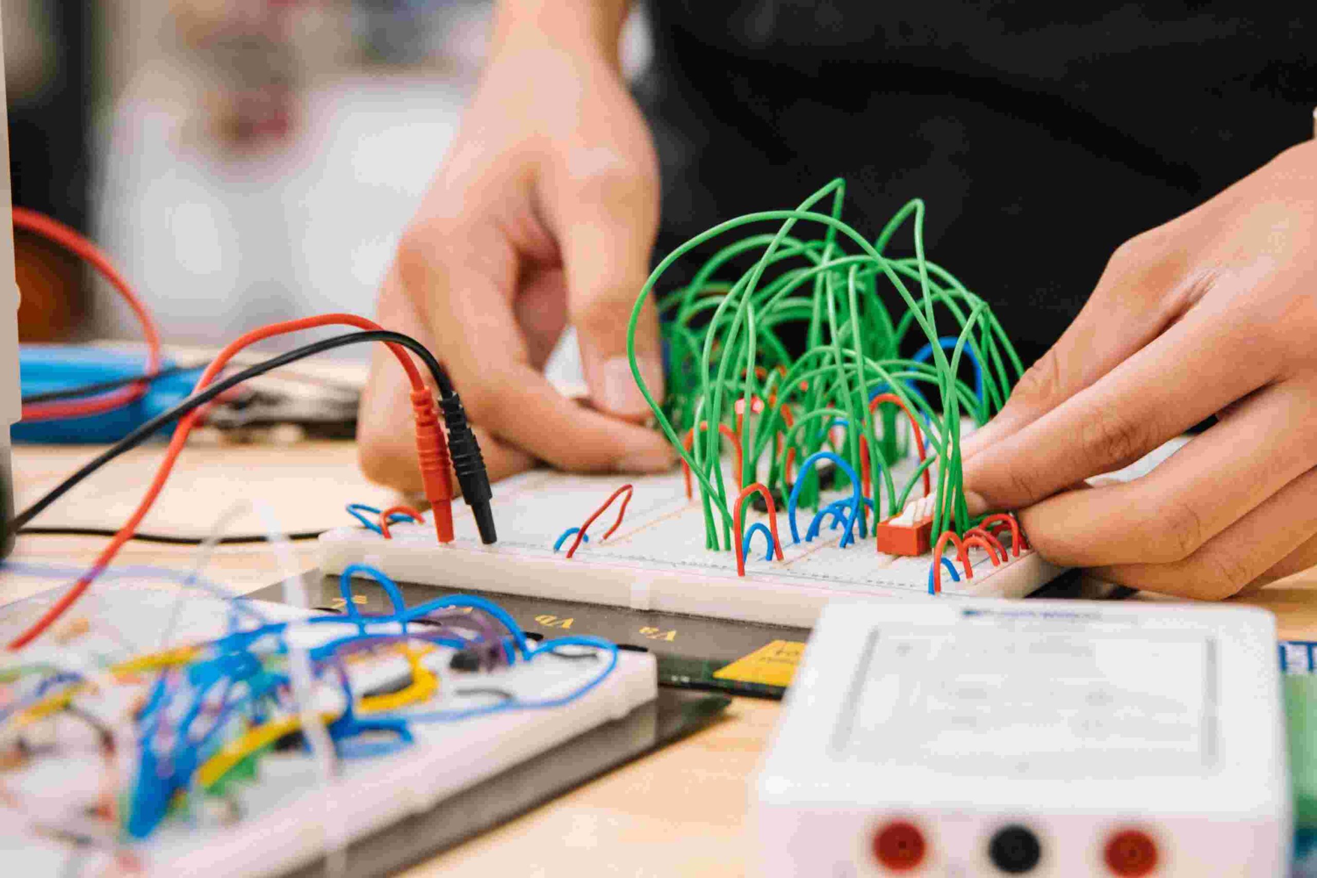
Wiring & Assembly
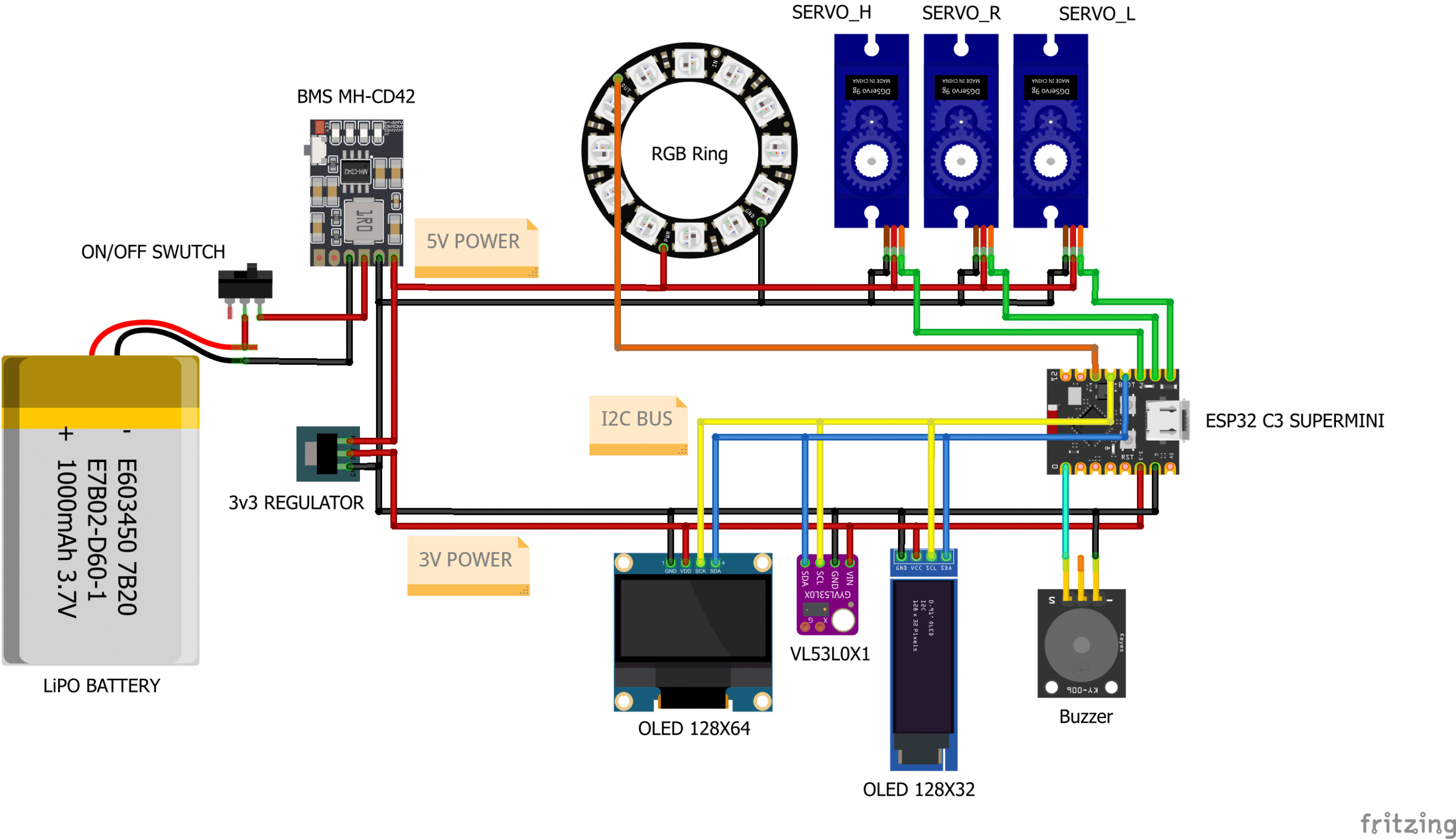
Wiring Diagram:
Wiring the Connections

Step 1: Power Supply and ON/OFF Switch
Connect the LiPo battery to the BMS MH-CD42 module.
- Connect the positive (+) terminal of the LiPo battery to the “+” input on the BMS.
- Connect the negative (-) terminal of the LiPo battery to the “-” input on the BMS.
Add the ON/OFF Switch
- Cut the positive wire connected to the “+” on the BMS and Connect it to one end of the ON/OFF Switch.
- Connect the other end of the ON/OFF Switch to the “+” output on the BMS.
Step 2: Power Distribution
Connect the BMS output to the Servos.
- Connect the “+” on the Servos to the “+” output on the BMS.
- Connect the “-” on the Servos to the “-” output on the BMS.
Connect the BMS output to the WS2812 Neopixel Ring.
- Connect the “+” on the RGB Ring to the “+” output on the BMS.
- Connect the “-” on the RGB Ring to the “-” output on the BMS.
Connect the output of the BMS to the 3.3V Regulator.
- Connect the “+” output of the BMS to the input of the 3.3V regulator.
- Connect the “-” output of the BMS to the ground pin of the 3.3V regulator.
Step 3: Powering the ESP32, OLEDs and ToF Sensor
- Connect the 3.3V output from the regulator to the VCC (or 3.3V) pin on the ESP32.
- Connect the GND from the regulator to the GND pin on the ESP32.
- Connect the GND from the regulator to the GND pin on both OLED displays and the VL53L0X1 sensor.
- Connect the 3.3V regulator output to the OLEDs and ToF Sensor.
- Connect the 3.3V output from the regulator to the VCC pin on both OLED displays and the VL53L0X1 sensor.
Step 6: Signal Connections
Connect the I2C communication lines.
- Connect the SDA pin of the ESP32 to the SDA pin of both OLED displays and the VL53L0X1 sensor.
- Connect the SCL pin of the ESP32 to the SCL pin of both OLED displays and the VL53L0X1 sensor.
Connect the signal pins of the servos to the ESP32.
- Connect the signal wire of SERVO_R to digital pin 6 on the ESP32.
- Connect the signal wire of SERVO_L to digital pin 5 on the ESP32.
- Connect the signal wire of SERVO_H to digital pin 7 on the ESP32.
Connect the WS2812 LED Ring and the Buzzer.
- Connect the signal wire of the RGB ring to digital pin 10 on the ESP32.
- Connect the signal wire of the Buzzer to digital pin 0 on the ESP32.
Assembly
- Break of down the assembly process into manageable steps.
- Use detailed images or animations to illustrate each step.
- Explain how to connect each component to the ESP32.
Component Placement:
- Show how to mount the components onto the 3D printed chassis.
- Consider cable management to ensure a clean and organized build.
Testing the Connections:
- Instructions on how to test the power supply and the connection of each component.
Troubleshooting:
- Tips on diagnosing possible issues with the electronics circuit.
Enclosure Mounting:
- How to mount components in the enclosure and wiring recommendations.
Architecture
The ESPRESSO project implements an Open-Source modular, extensible architecture for an ESP32-C3 based IoT robot with distance sensing, motor control, OLED display, RGB LED status indication, Buzzer and web-based control interface.
Current Architecture
ESPRESSO’s modular architecture provides a solid foundation for expansion with additional sensors and actuators while maintaining code organization and system reliability.
Core Components
- DistanceSensor – VL53L0X ToF sensor with error handling and validation
- MotorControl – Servo-based motor control for movement
- OLEDDisplay – SSD1306 display for status information (optional)
- RGBLed – WS2812 NeoPixel for visual status indication (optional)
- Buzzer – Piezo Buzzer for sound indication (optional)
- WebService – Async web server for remote control
Infrastructure
- RobotConfig.h – Centralized configuration management
- I2CManager – Shared I2C bus management (singleton pattern)
- ComponentTemplate.h – Template for creating new components
Pin Assignments
| Component | Pin | Type | Notes |
|---|---|---|---|
| I2C SDA | 8 | I2C | Shared bus for ToF + OLED |
| I2C SCL | 9 | I2C | Shared bus for ToF + OLED |
| Left Motor | 5 | PWM | Continuous Servo control |
| Right Motor | 6 | PWM | Continuous Servo control |
| Vertical Servo | 7 | PWM | Servo control |
| RGB LED | 10 | Digital | WS2812 data line |
| Buzzer | 4 | Digital | Future expansion |
| Button | 3 | Digital | Future expansion |
Available Pins for Expansion
Pins 0, 1, 2, 18, 19, 20, 21 are available for additional components.
I2C Devices
- 0x29: VL53L0X Distance Sensor (default address)
- 0x3C: SSD1306 OLED Display (128×64)
Features
🛡️ Robust Error Handling
- Component initialization validation
- Graceful degradation when components fail
- Error counting and recovery mechanisms
- Comprehensive status reporting
🔄 Modular Component System
- Independent component lifecycle management
- Optional components don’t break system operation
- Shared resource management (I2C bus)
- Update timing control per component
📱 Enhanced Web Interface
- Real-time distance display with bar graph
- Manual robot control with directional buttons
- Autonomous mode with obstacle avoidance
- Visual status indicators and connection info
🚦 Multi-Modal Status Indication
OLED Display: Text-based system information
RGB LED: Color-coded status indication
– Blue: Connected/Ready
– Green: Manual mode
– Cyan: Autonomous mode (breathing effect)
– Yellow: Warning (blinking)
– Red: Error/Emergency (fast blink)
🤖 Intelligent Autonomous Mode
- Configurable distance thresholds
- Three-stage obstacle avoidance:
– Normal speed when clear (>15cm)
– Reduced speed when approaching (10-15cm)
– Stop and turn when too close (<5cm) - Sensor validation and error handling
Component Independence
Each is designed to be independent:
- Self-contained initialization and error handling
- Optional operation (system continues if component fails)
- No direct dependencies between hardware components
- Shared resources properly managed
Configuration Management
All settings centralized in RobotConfig.h:
namespace RobotConfig {
    const int I2C_SDA_PIN = 8;
    const int I2C_SCL_PIN = 9;
    // ... other configurations
}
I2C Bus Sharing
The I2CManager singleton ensures proper sharing:
I2CManager* i2c = I2CManager::getInstance();
if (!i2c->isInitialized()) {
    i2c->begin(RobotConfig::I2C_SDA_PIN, RobotConfig::I2C_SCL_PIN);
}
Adding New Components
Step 1: Define Configuration
Add to RobotConfig.h:
namespace NewComponentConfig {
    const int PIN = 11;
    const int UPDATE_INTERVAL_MS = 100;
}
Step 2: Create Component Class
Use ComponentTemplate.h as a starting point:
class NewComponent {

private:

    bool isEnabled;
    unsigned long lastUpdate;

    // Component-specific members

public:

    NewComponent(int pin);
    bool init();
    void update();
    void reset();
    void enable() { isEnabled = true; }
    void disable() { isEnabled = false; }
    bool isReady() const { return isEnabled; }
    String getStatus() const;
};
Step 3: Implement Core Methods
- init(): Hardware initialization and validation
- update(): Regular component updates with timing control
- reset(): Error recovery and reinitialization
- getStatus(): Diagnostic information
Step 4: Integrate with Main System
Add to main .ino file:
#include "NewComponent.h"
NewComponent newComp(RobotConfig::NewComponentConfig::PIN);


void setup() {
    // ... other initialization
    if (!newComp.init()) {
        Serial.println("WARNING: NewComponent not available");
    }
}

void updateComponents() {
    // ... other updates
    if (newComp.isReady()) {
        newComp.update();
    }
}
Programming
Software Setup:
- Instructions on how to install the Arduino IDE or other required software.
- Explain how to install the necessary libraries for the ESP32, sensors, and actuators.
Code Overview:
- Describe the structure of the code and the main functions.
- Explain how the code controls the robot’s behavior.
Uploading the Code:
- Provide clear instructions on how to upload the code to the ESP32.
Example Code Snippets:
- Include code snippets that demonstrate how to read sensor data, control the servos, and display information on the OLED.
Customization and Expansion:
- Suggest ideas for customizing the code and adding new features (e.g., remote control, autonomous navigation, voice control).
- Different software implementations.
- Library recommendations.
- Suggest ideas for customizing the code and adding new features (e.g., remote control, autonomous navigation, voice control).